
The product
Mechanical flow switches technology
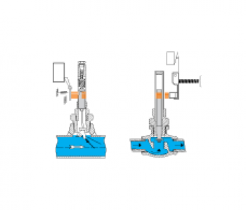
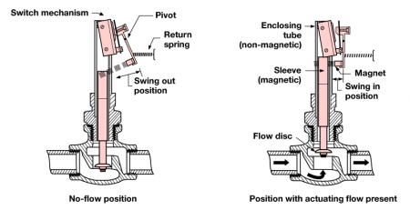
F10: Force of liquid or gas flow against a vertical flow vane mounted in a line causes the vane to pivot to a horizontal position, moving an attraction sleeve into the field of a switch magnet. This pulls the magnet toward the sleeve and actuates the switch.
F50: The force of liquid flow through a valve body and against a flow disc causes it to lift out of the flow path. The attraction sleeve at the top of the disc assembly moves into the field of a switch magnet, attracting the magnet and actuating the switch.
Features
- No calibration required
- Bronze or stainless steel construction
- Process pressures to 1150 psig (79 bar)
- Process temperatures to +750°F (+400°C)
- Actuation on increasing or decreasing flow
- In-line mounting
- Bodies for flow lines from ¾” to 2”
Options
- Dry contact or hermetically sealed switches
- Actuation flow rates from 0.8 to 24.8 gpm
Operating principle
The rate of flow through the valve body raises or lowers the disc. This in turn raises or lowers the magnetic sleeve, within its sealed non-magnetic barrier tube. On an increasing flow rate, the magnetic sleeve rises into the field of the permanent magnet, located outside the barrier tube, actuating the attached switch mechanism. When the flow rate drops, below the rate for which the flow disc is calibrated, a reversal of this action occurs.
Approvals
| ATEX | Ex d, Ex ia |
| CCOE | Ex d |
| CSA | XP |
| FM | XP |
| EAC (GOST) | Ex d, Ex ia |
| IEC | Ex d, Ex ia |
| Inmetro | Ex d |
| Korea | Ex d |
| NEPSI | Ex ia, CPA |
Other approvals are available. Consult factory for more details.
request quote